For many years while I was growing up, I had always wanted to be able to create my own electrical circuits but kept on running into hurdle after hurdle.
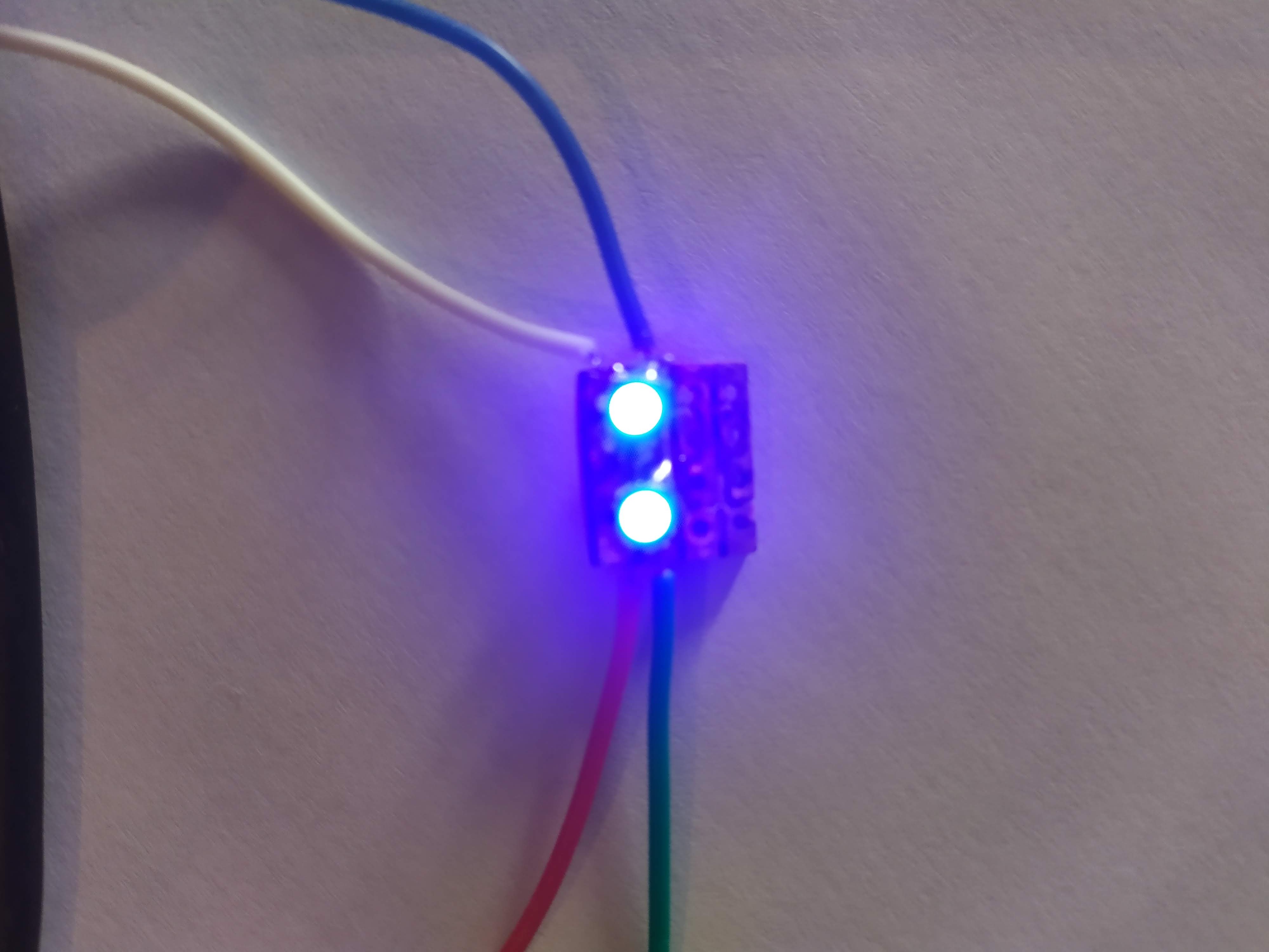
After trying to use SMT RGB LEDs on prototype boards with multiple long, tedious, and non cost-effective failures, I decided I need to step up a notch and actually manufacture boards.
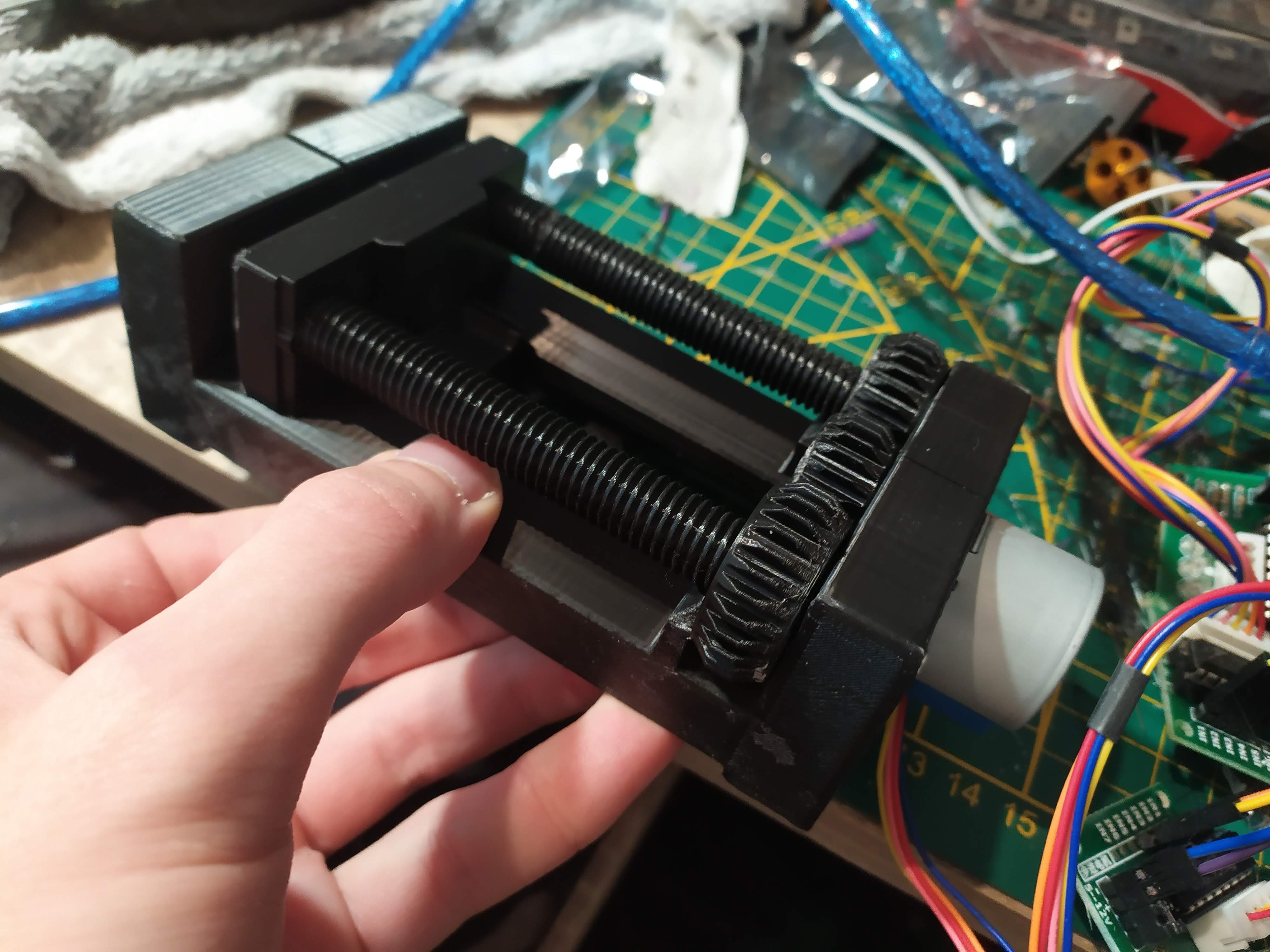
I bought a 12V spindle motor and wanted to build an almost fully 3D printed CNC, based on a 3D printed vice mechanism found on thingiverse, except that I couldn’t get the motor to turn once mounted – the mechanism was simply too tight and in the end the screw spirals snapped. I would like to try again in the future, maybe using my current CNC setup for certain parts.
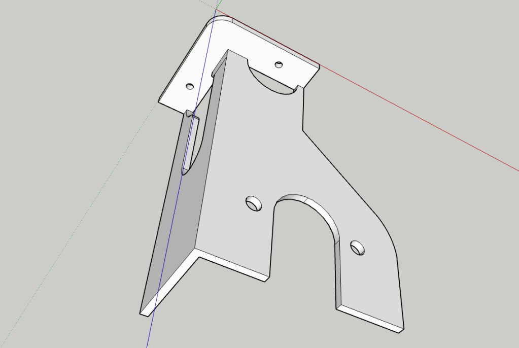
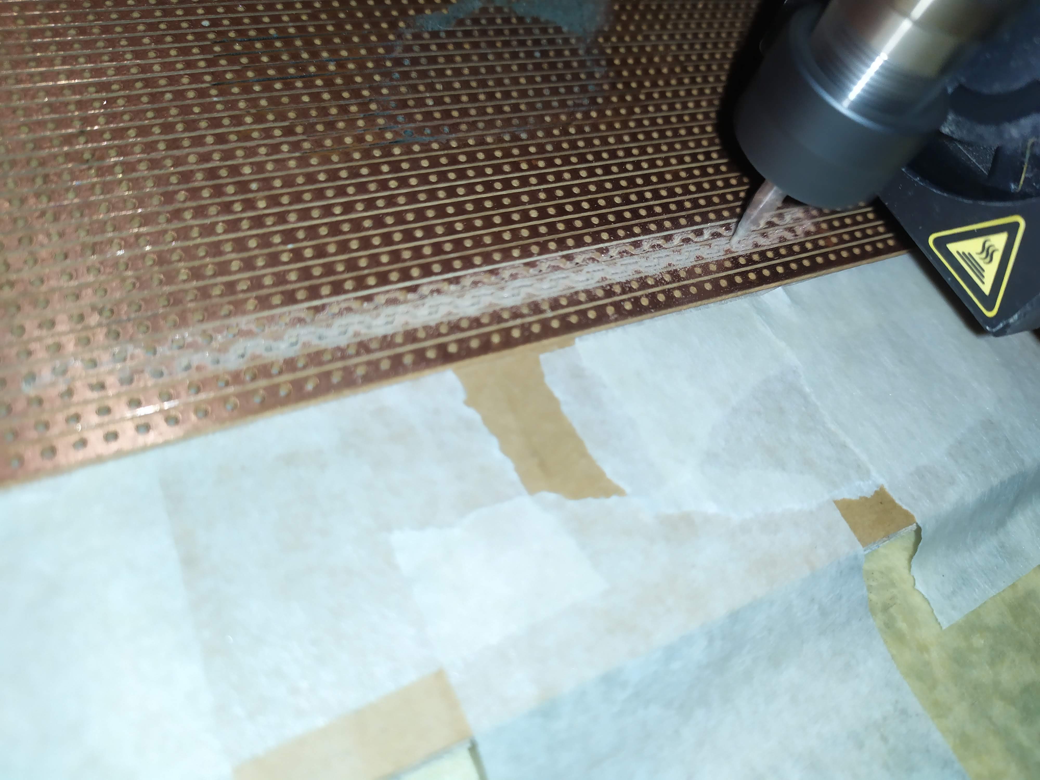
The next option was to mount the spindle motor on my Creality CR-10 S 3D printer, so I made a 3D model and printed it. As you can see in the later pictures, this didn’t go well, so to save time I fixed the part and added reinforcements using a dedicated soldering iron at 200°C (PLA filament).
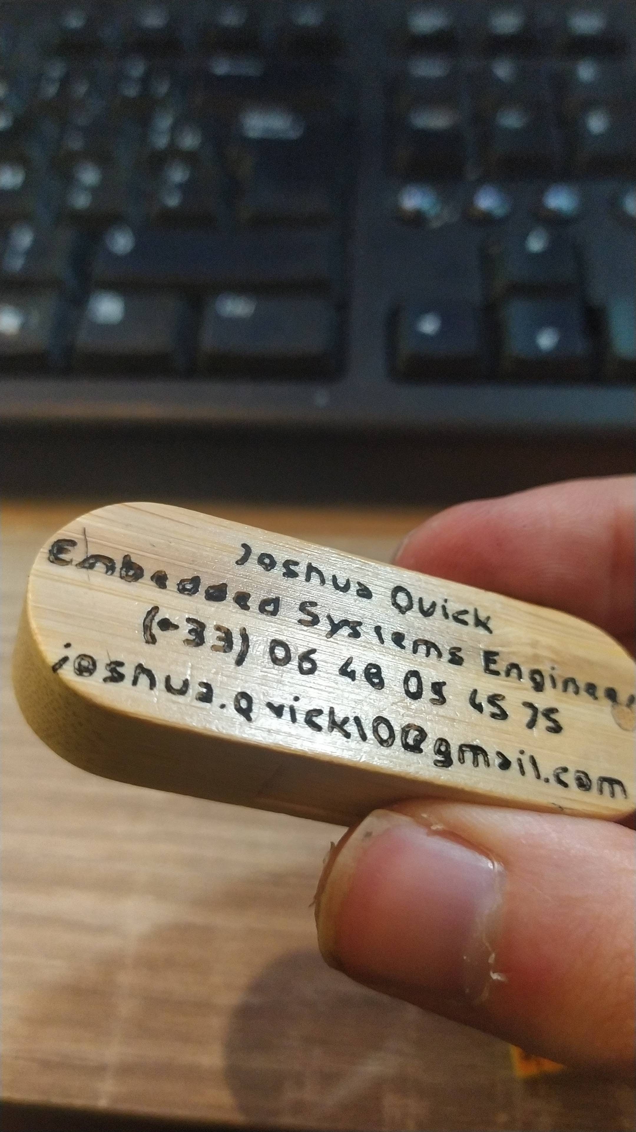
As a first test, I decided to engrave my bamboo usb key. I had to cancel it a few times, and modify the cutout models, but the result is great (the text is polygonal because of me).


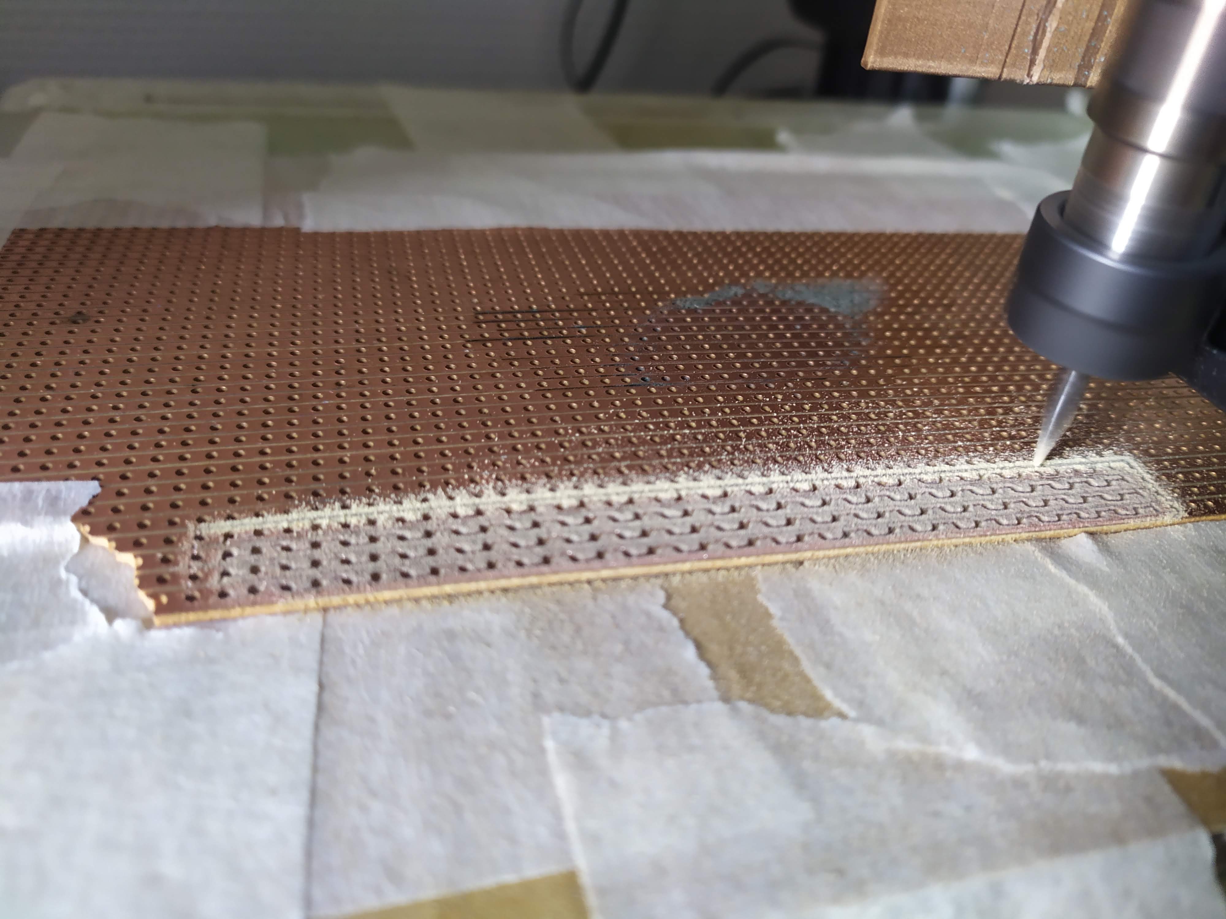
To draw the paths the drill bit will go past, I installed FlatCAM, and it works great. All I need to do is add M211 S0 at the beginning of the exported gcode (ignores endstops, makes negative coordinates possible), and change F to G0 F.
I then position the drill bit where I want the CNC to start, turn the 3D printer off to reset the coordinates, then run the gcode. I can run multiple gcode files one after the other if I want and the printer keeps the same point of origin.
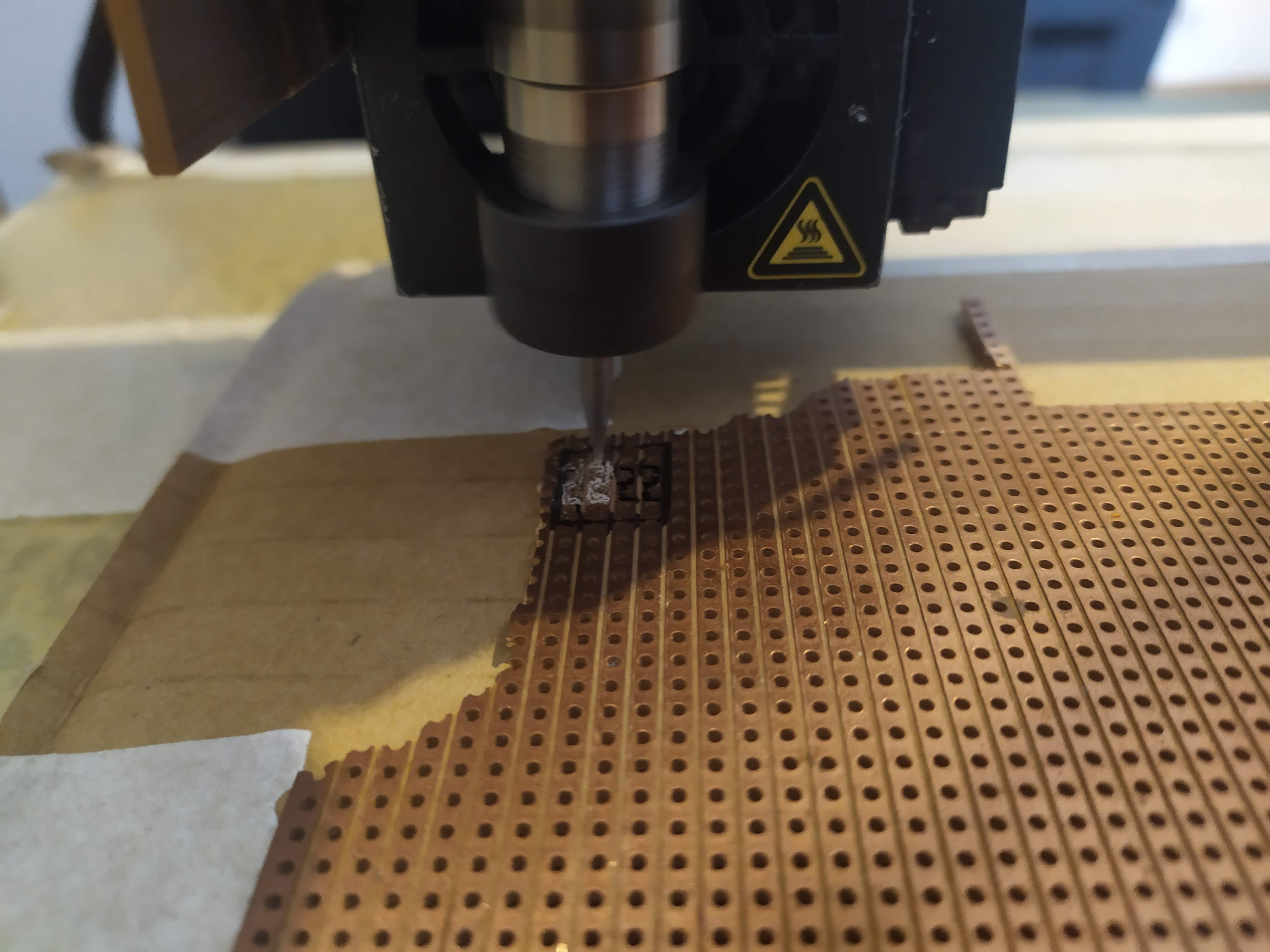
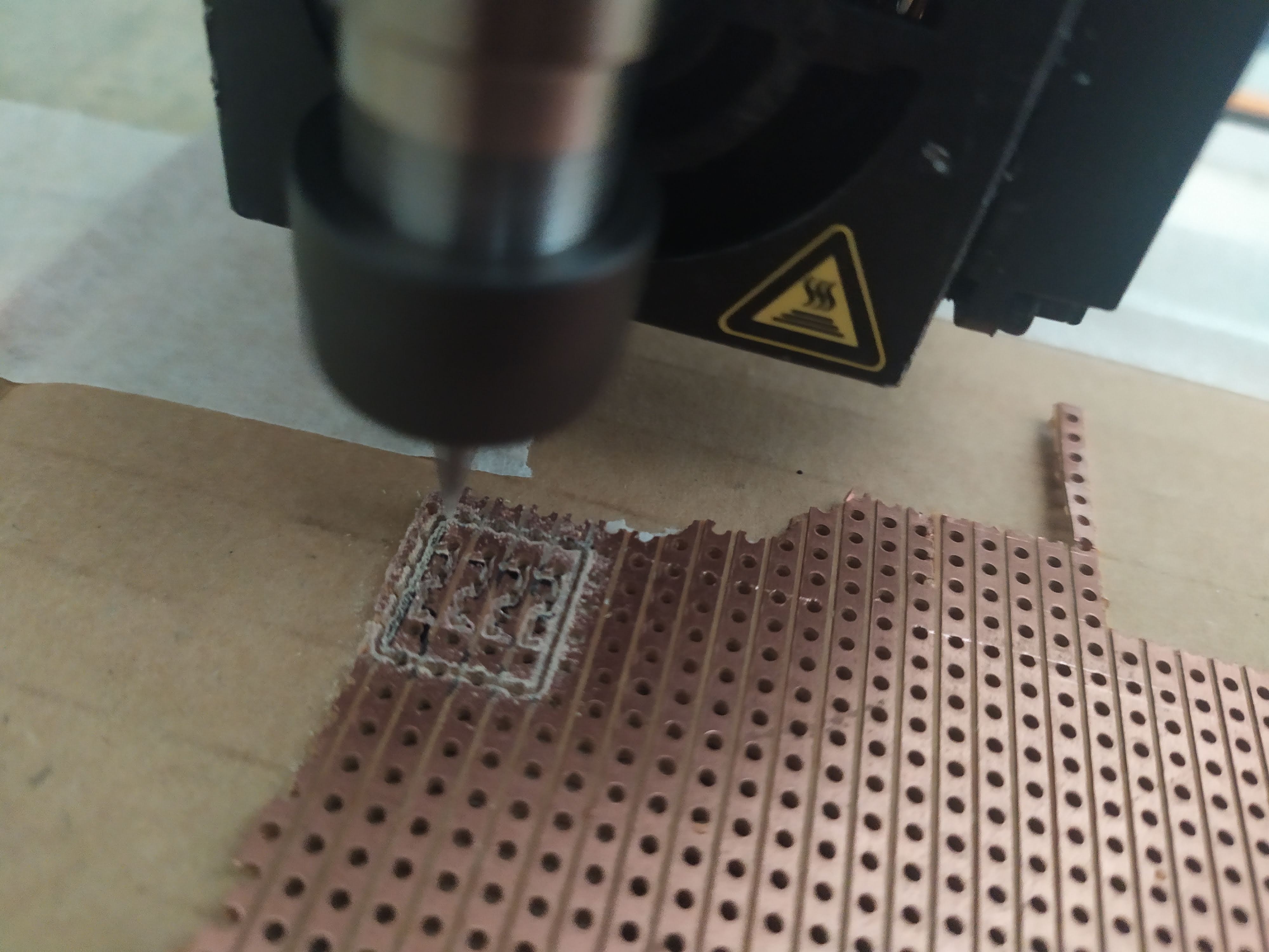

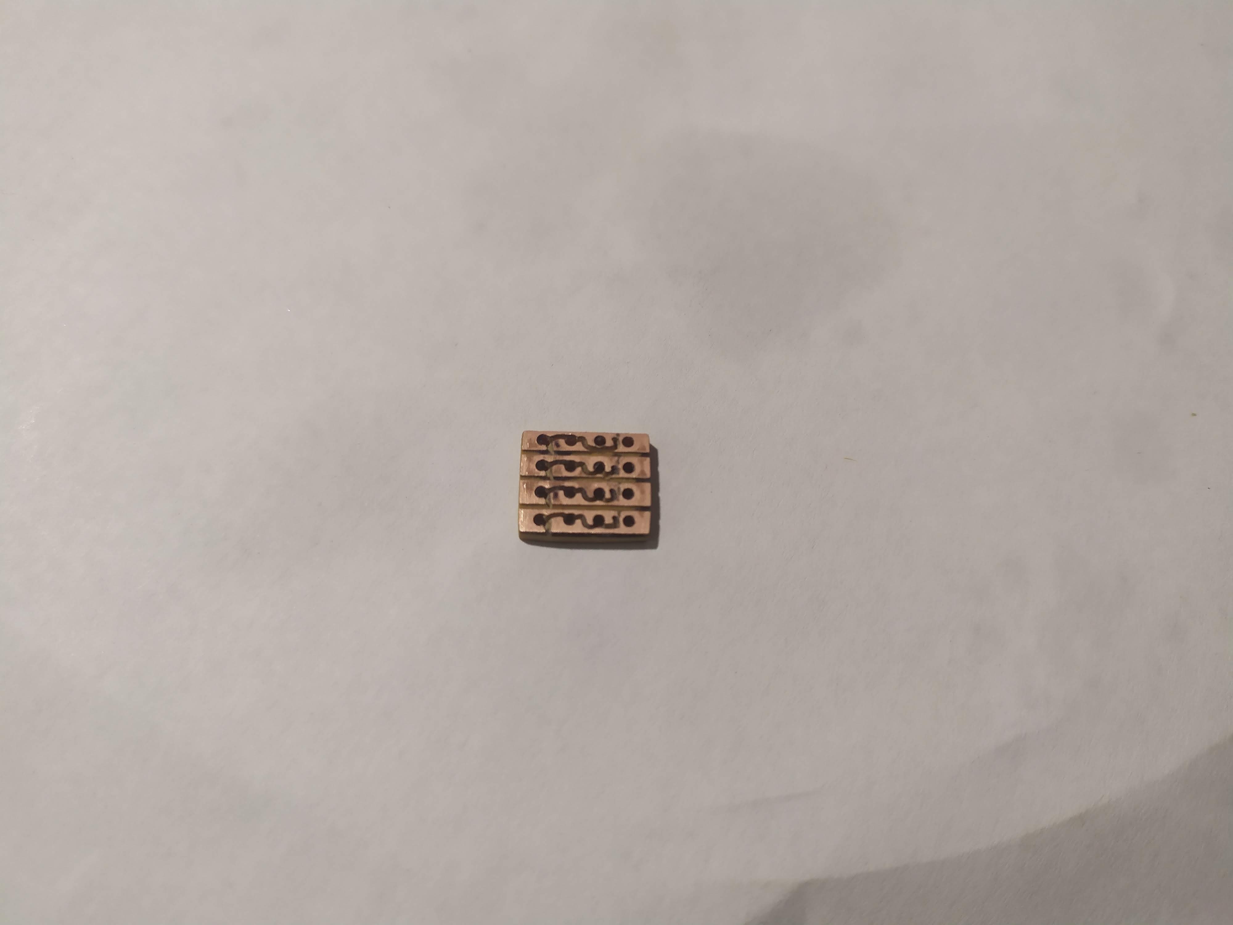
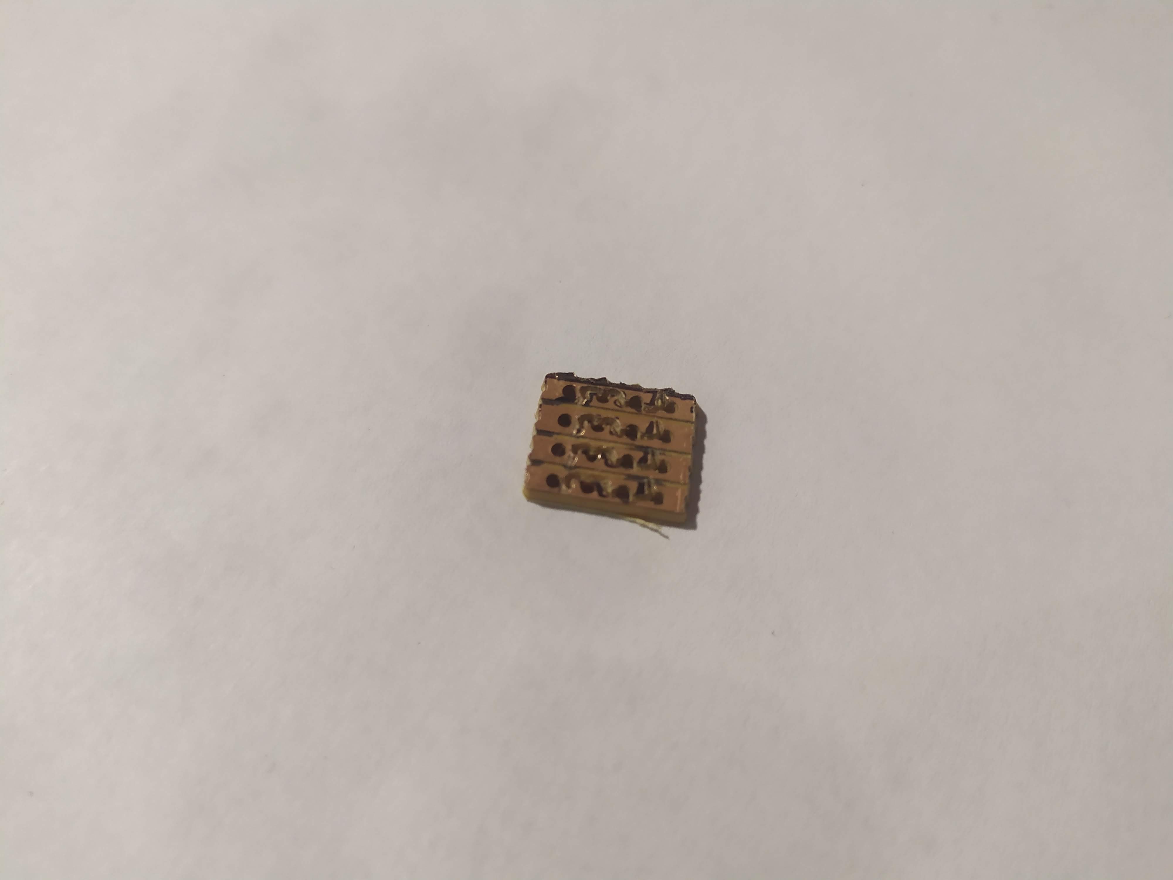
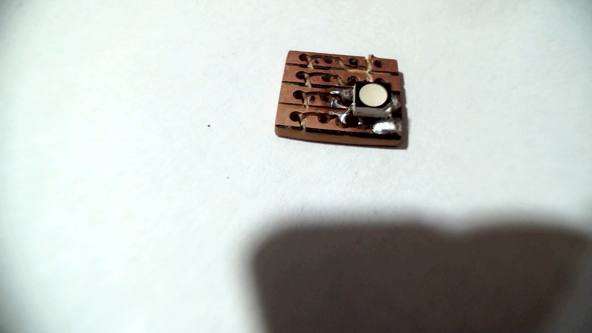
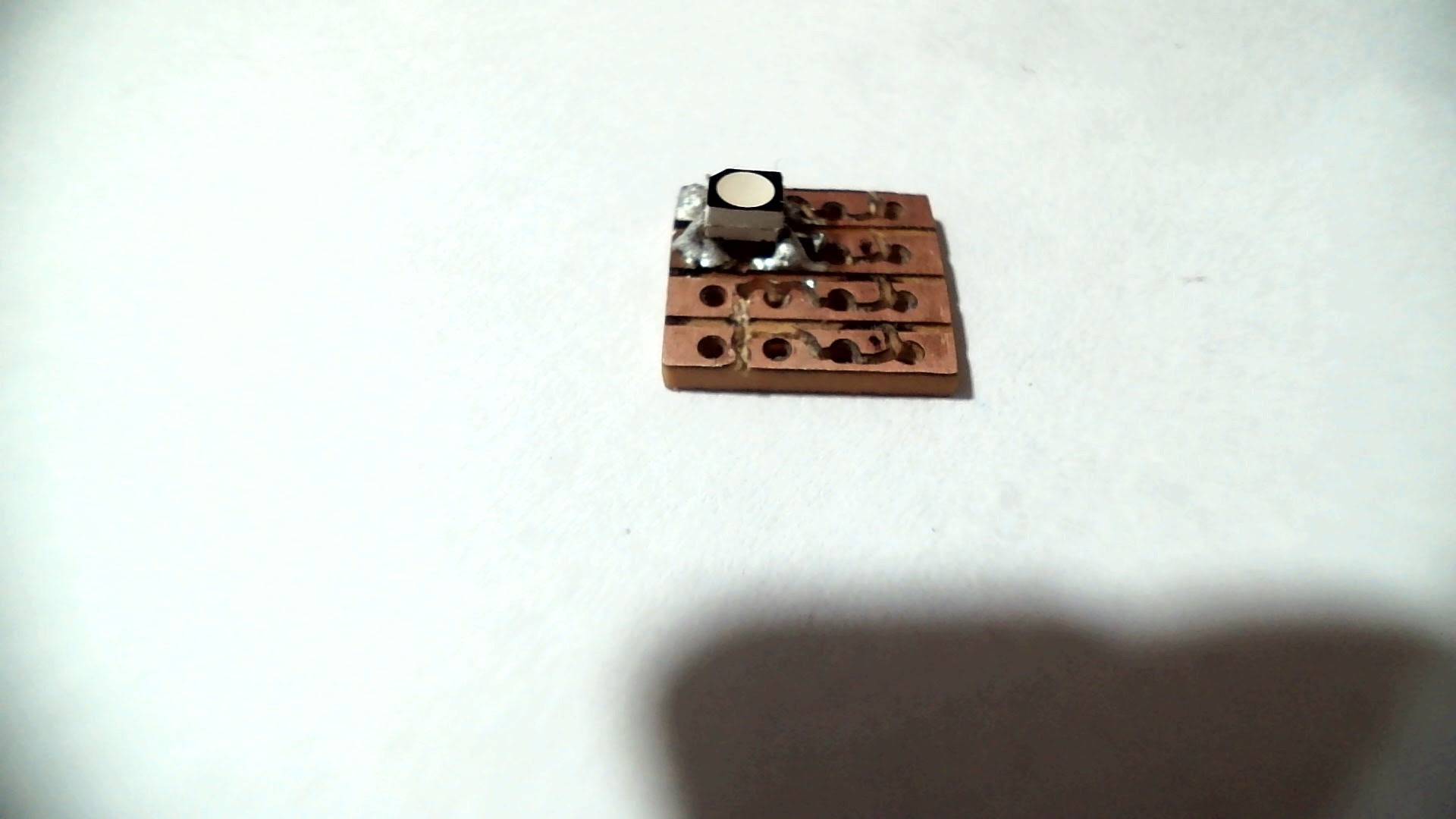
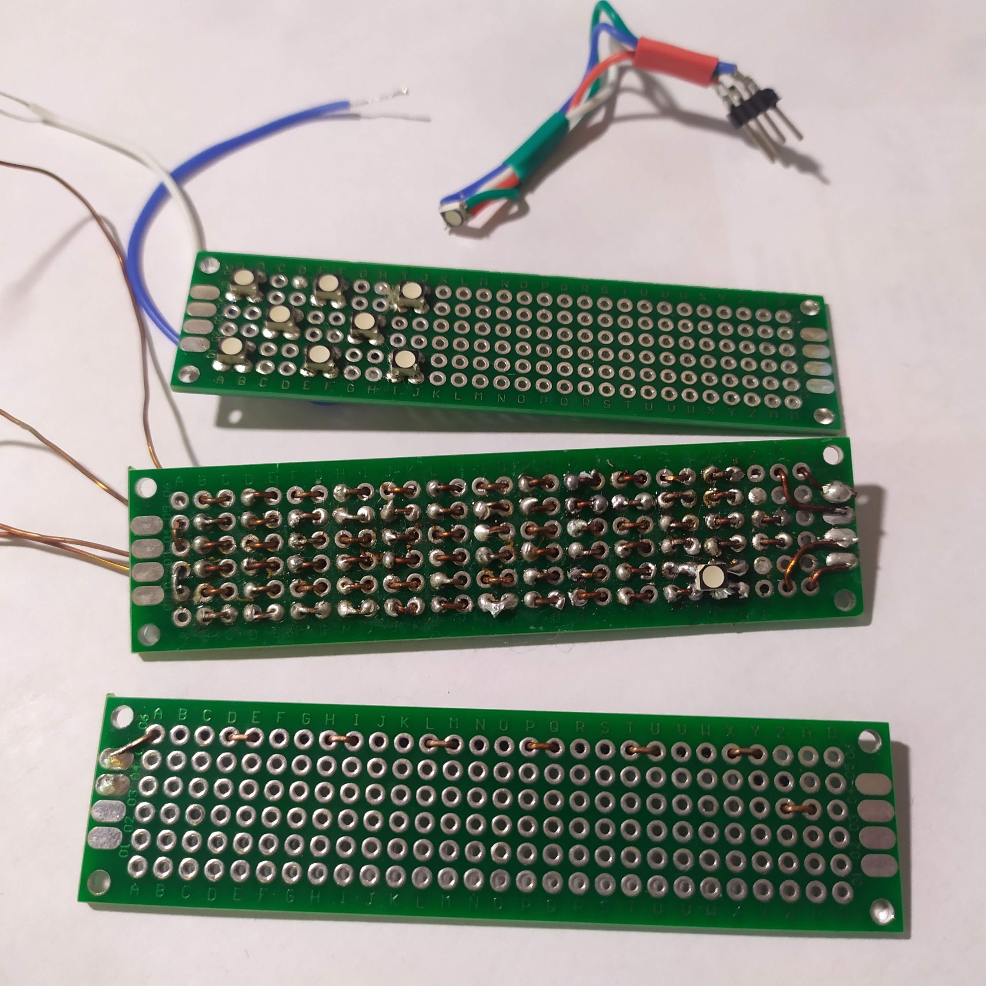
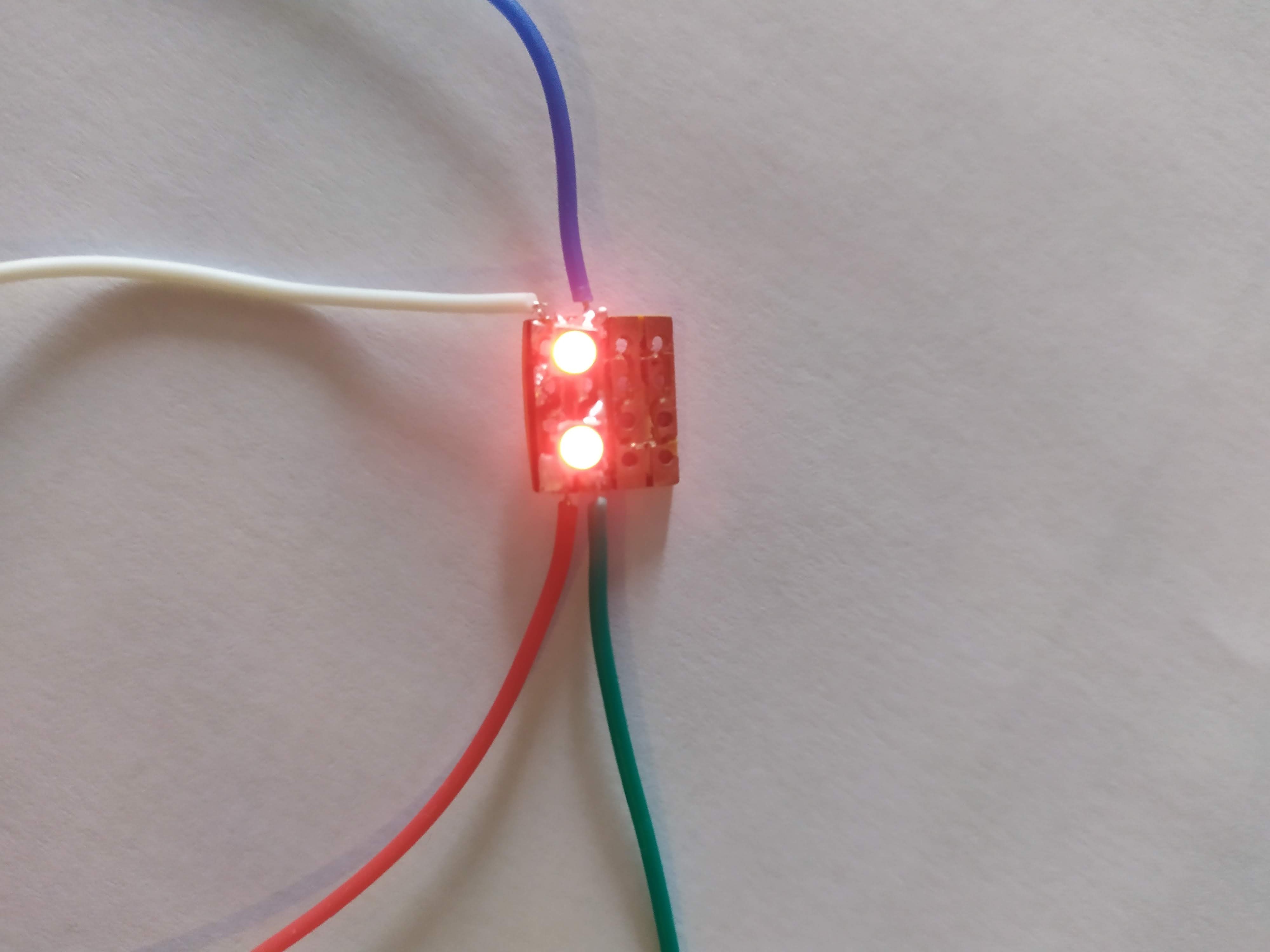
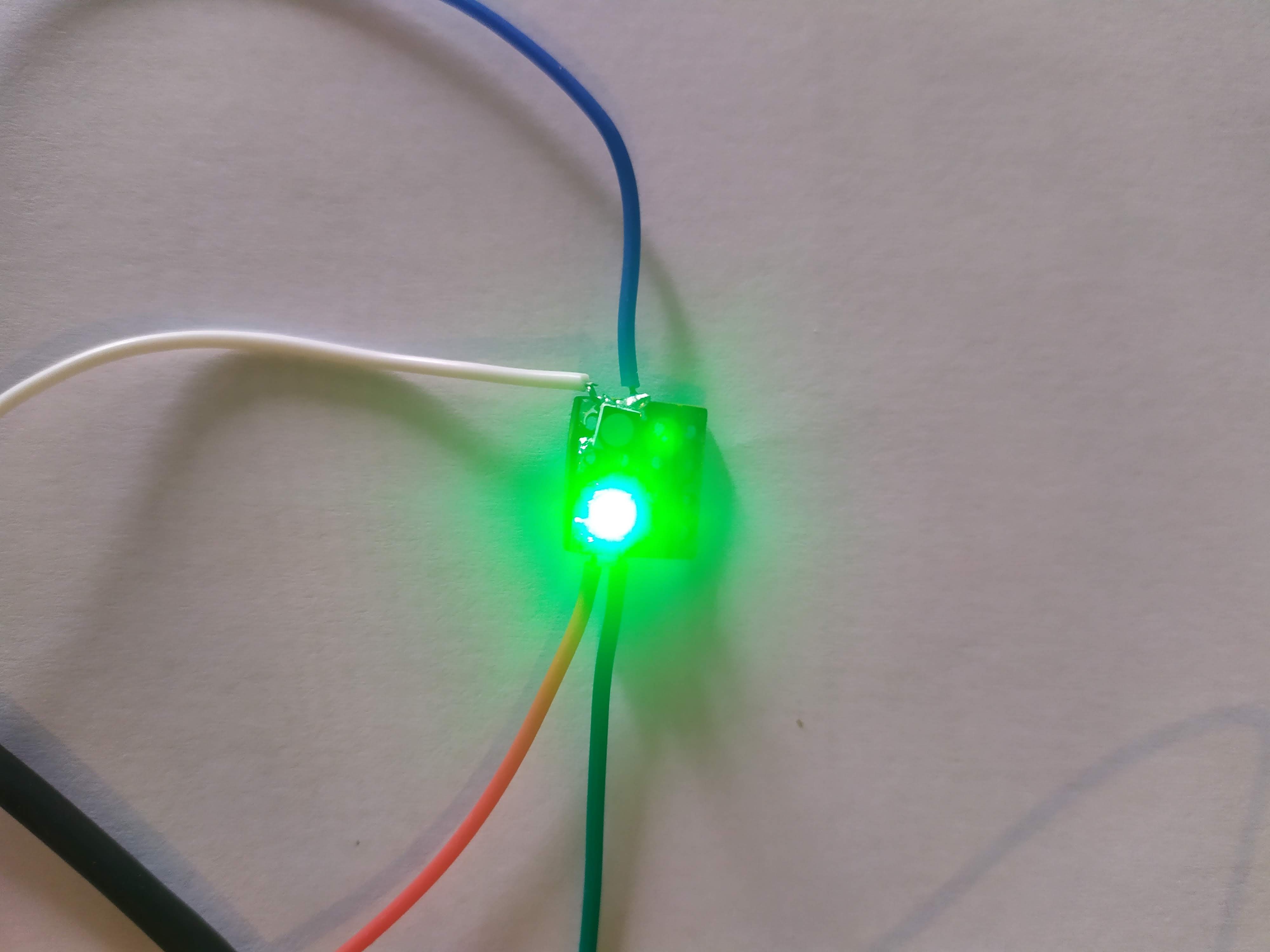
I used prototyping board because I don’t have any copper boards yet; unfortunately, my measurements were slightly off and the trace for the green LED was cut on the line I soldered on, and the other line was unusable. Here are the results :
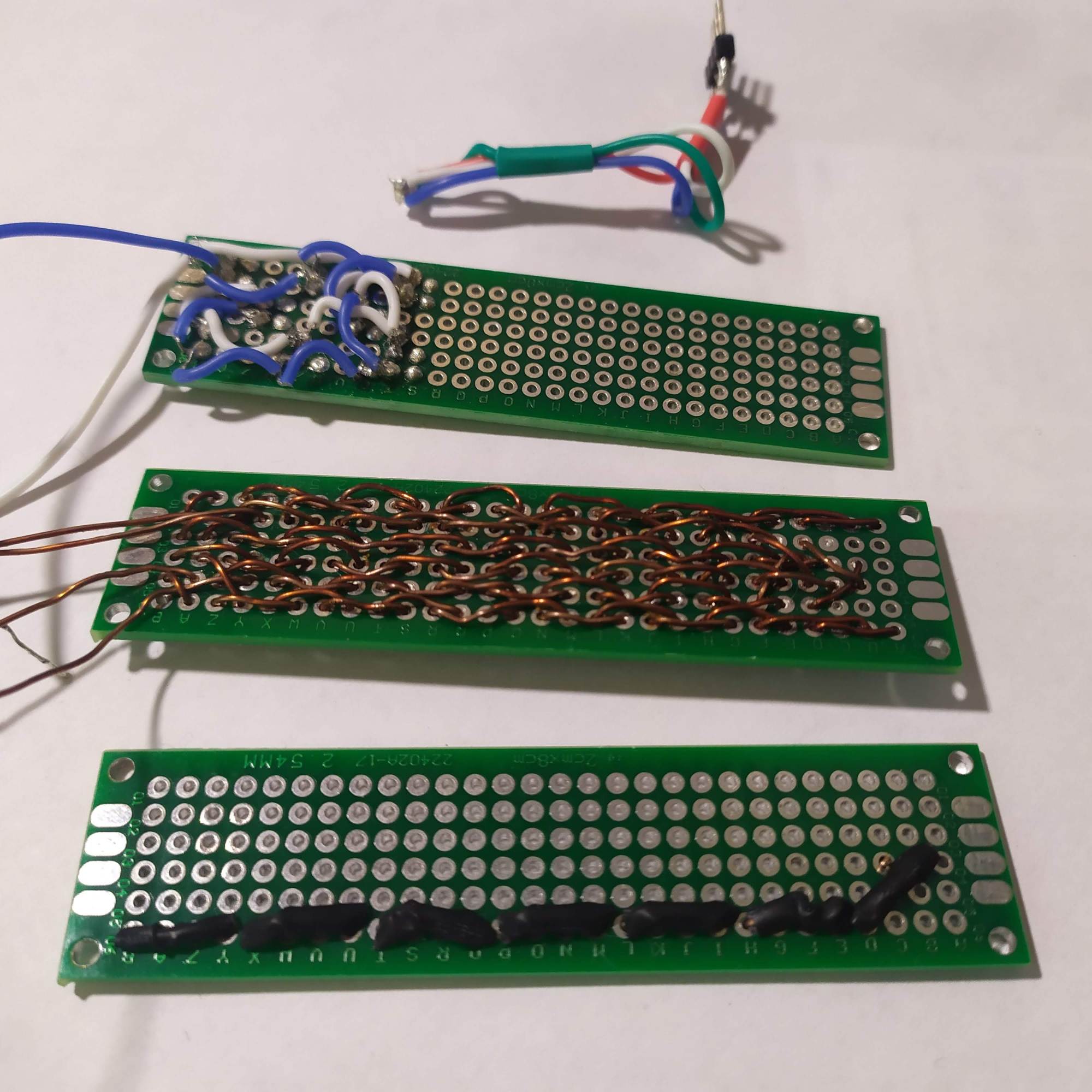
After measuring in a more precise manner, I increased the scale of the engraving and aligned the holes to maximise the copper surface.

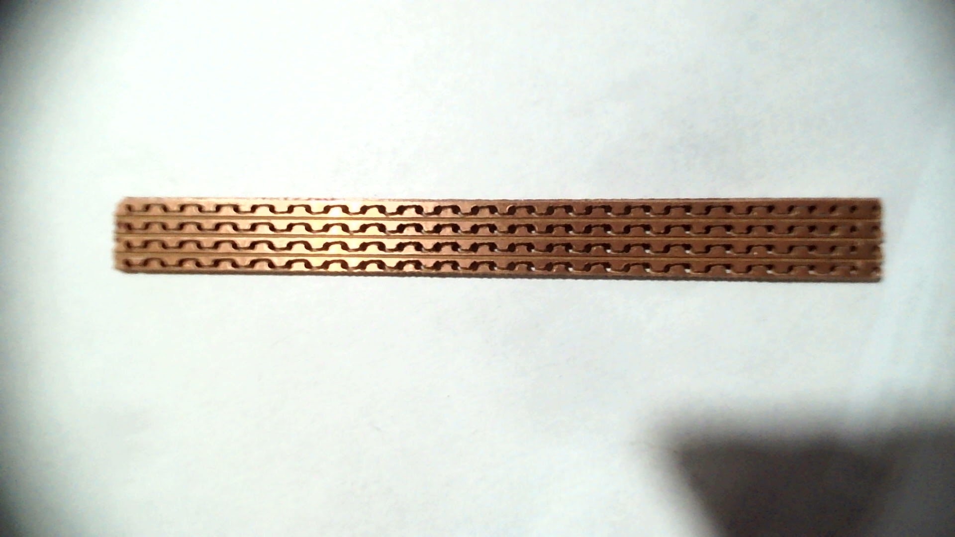
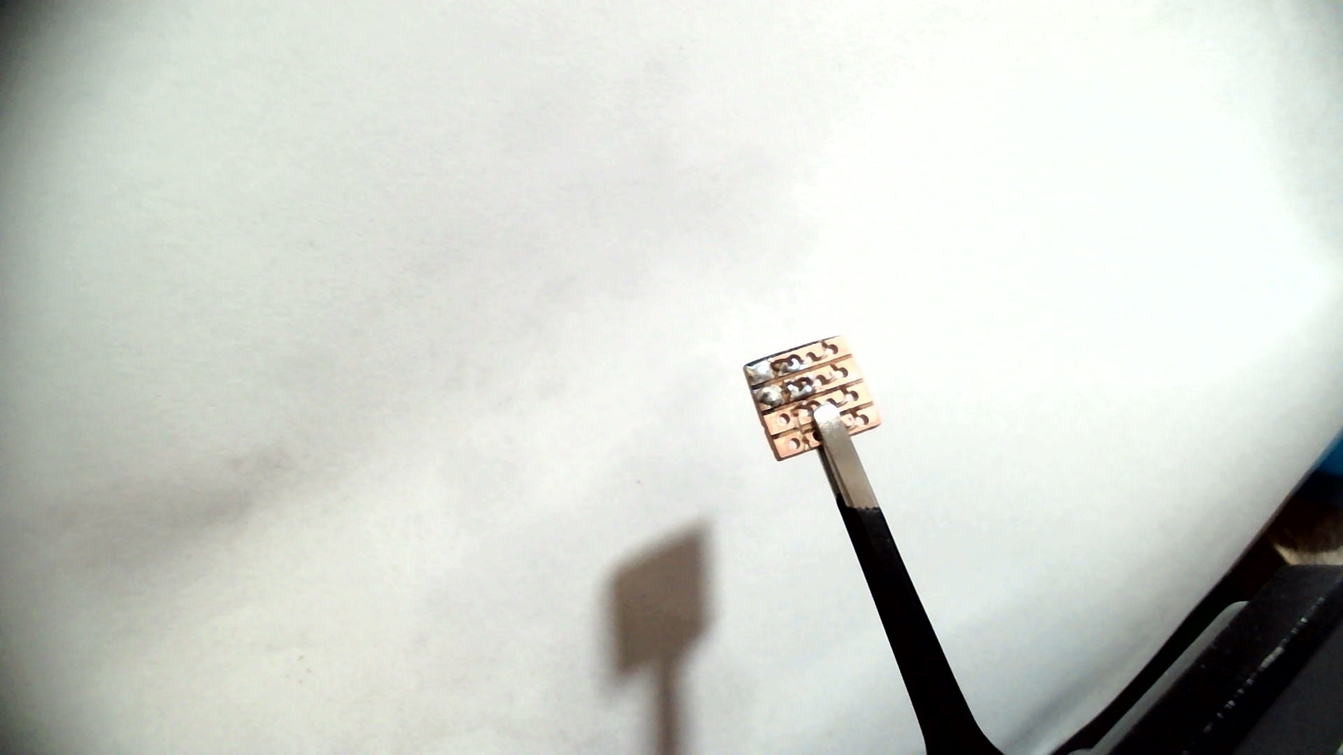
I was slightly worried because the traces on one of the edges were really thin, but after a continuity check, everything is connected the way they should be.
Conclusion
I’m going to have a hard time soldering all of this correctly, but once it’s done, I’ll tackle the power circuit and some 3D printed housing.
I’m pretty satisfied with my new CNC functionality, but I need to fix it in place more firmly to avoid jumping, and create a rig to hold items in place and align them, maybe adding a gcode file that positions the head in the center of the rig.
Don’t hesitate to say in the comments if you have any ideas, suggestions, or remarks. See you in another post!
